Manual of Ice (MANICE): Chapter 3
Chapter 3: Observed Ice Charts
- 3.1: Preparation of Ice Charts
- 3.2: Dissemination of Aerial Ice Charts
- 3.3: Dissemination of Shipboard Ice Charts
- 3.4: The Egg Code
- 3.5: Symbols Used on Ice Charts
- 3.6: Supplementary Procedures for Indicating Total Concentration
- 3.7: Colour Coding Ice Charts
- 3.8: Examples of the Use of the Egg Code
This chapter deals with basic procedures for preparing and transmitting ice charts. Ice charts are of importance to icebreaker captains, commercial shipping interests and fishing vessels to assist them in finding the easiest passage through the ice or to avoid the ice when feasible to do so. The data on the chart is of vital importance to ice forecasters, serving as the basis for:
- ice hazard warnings
- preparation of daily ice analysis chart
- short- and long-range ice forecasts and seasonal outlooks
- preparation of regional ice charts
3.1 Preparation of Ice Charts
Time and care are necessary to prepare ice charts. Details and precision are of the utmost importance.
3.1.1 Drawing Procedures
Ice charts are drawn directly on a computer screen using Geographical Information Systems software. This software has been developed specifically for the Coast Guard to allow precise observation and quick transmission of data.
It is beyond the scope of this manual to describe this particular software in detail. It is sufficient to know the precision of observation is greatly increased by the use and integration of the Global Positioning System (GPS). The usefulness of the data is enhanced by the automatic verification of all coding and final preparation of charts.
Data will generally be transmitted in the form of electronic files and distributed by Canadian Ice Service to clients. Maps of observed data will also be produced by Canadian Ice Service and made publicly available.
3.2 Dissemination of Aerial Ice Charts
Data (in the form of electronic files or charts) is of special importance to the ice forecasters and analysts and ships operating in or near the areas observed during the reconnaissance mission. Files are updated continuously while airborne and sent frequently. Partial files, rough copies and final copies of charts may be sent in-flight to the Canadian Ice Service, the appropriate Coast Guard ice offices and Coast Guard ships as necessary.
After the termination of the reconnaissance mission, the Ice Service Specialist will transmit the completed and corrected data to the Canadian Ice Service for distribution.
3.3 Dissemination of Shipboard Ice Charts
An Ice Service Specialist serving on icebreakers equipped with appropriate communication equipment should relay their ice information (even if incomplete) before 1800 UTC to Canadian Ice Service. Upon completion of the duty day, a second transmission is recommended. The data should be sent in the form of an electronic file via cellular phone, landline or satellite link depending on what is practical and available.
If it is not possible to transmit an electronic file, then a map could be printed and send by facsimile.
3.4 The Egg Code
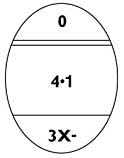
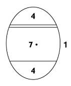
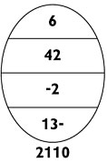
The basic data concerning concentrations, stages of development (age) and form (floe size) of ice are contained in a simple oval form. A maximum of three ice types is described within the oval. This oval and the coding associated with it, are referred to as the “Egg Code”. To indicate ice observations interpreted from radar imagery, the oval shall be omitted.
In the following figures and tables where ranges are shown for thickness, floe sizes or other dimensions, a report coinciding with the end point of a range shall be coded as the higher value.
The following is a summary diagram of the Egg Code. This code conforms to international convention and shall be used in coding all visual sea ice and lake ice observations without exception.

The symbols CaCbCc and FaFbFc correspond to Sa Sb Screspectively.
There are some minor additions to the egg code symbology that are Canadian practice. In Canada, to enable the reporting of additional ice classes, especially during freeze-up and break-up, Cd Se and Fe can be used. This should not be a common occurrence.
The following pages describe the specific details and rules for completing each level of information within the egg.
3.4.1 Concentration (C)

Total concentration (Ct ) of ice in the area reported in tenths and partial concentrations of thickest (Ca), second thickest (Cb), third thickest (Cc) and fourth thickest (Cd) ice in tenths.
Notes:
- Less than 1/10 (i.e. traces) shall not be reported within the oval except to describe open water (see Example 1, section 3.8).
- Cd shall only be included when Sd and Seare reported (see Example 2, section 3.8).
- When Sd is used and Cd is omitted, Cd equals Ct-(Ca+Cb+Cc) (see Example 3, section 3.8).
- When only one ice type is present, the partial concentration shall not be indicated (see Example 4, and Example 5, section 3.8).
- When one ice type is present with a trace of a thinner type, only total concentration of the major ice type shall be indicated (see Example 5, section 3.8 ).
3.4.2 Stage of Development (S)

Stage of development of thickest (So), second thickest (Sa), third thickest (Sb) and fourth thickest (Sc) ice and the thinner ice types Sd and Se, of which the concentrations are reported by CaCb Cc Cdrespectively.
Notes:
- Reference to thicker ice should be understood to mean older ice and conversely, thinner ice to mean younger ice types.
- Ice is designated as Sea, Lake or River Ice depending on where it forms. In Canada, the practice is to use lake-ice coding to report ice in the Great Lakes and the St. Lawrence Seaway. Elsewhere, including the St. Lawrence River east of Montreal, sea-ice coding is used for stages of development.
- Sa, Sb and Sc shall have concentrations of at least 1/10, except when Ct is zero (see Example 1, section 3.8).
- Reporting of Sa, Sb and Sc should generally be restricted to a maximum of three significant classes. In exceptional cases further classes may be reported as follows:
- So– Stage of ice development thicker than Sa, but having a concentration less than 1/10 (see Example 6, section 3.8).
- Sd– Stage of development of the thickest remaining ice types (if more than one type remains). It is the fourth stage present after Sa, Sb and Sc.
- Se– Shall only be reported when a thinner ice type remains after Sd. Partial concentration of Se is obtained by subtracting partial concentrations (CaCbCcCd) from total concentration (Ct) (see Example 2, section 3.8).
- When Se is not present,Sd may be a trace of ice (see Example 6, section 3.8).
- Concentration shall not be indicated for So and Se(see Example 2, section 3.8, and Example 6, section 3.8).
- Concentration shall not be indicated for Sd when Seis not present (see Example 3, section 3.8, and Example 5, section 3.8).
Table 3.1: Coding for Sea-Ice Stages of Development (SoSaSbScSdSe)
| Description | Thickness | Code |
| New ice | < 10 centimetres | 1 |
| Nilas, Ice rind | < 10 centimetres | 2 |
| Young Ice | 10 – 30 centimetres | 3 |
| Grey Ice | 10 – 15 centimetres | 4 |
| Grey-white ice | 15 – 30 centimetres | 5 |
| First-year ice | >= 30 centimetres | 6 |
| Thin first-year ice | 30 – 70 centimetres | 7 |
| First stage thin first-year | 30 – 50 centimetres | 8 |
| Second stage thin first-year | 50 – 70 centimetres | 9 |
| Medium first-year ice | 70 – 120 centimetres | 1· |
| Thick first-year ice | > 120 centimetres | 4· |
| Old ice | – | 7· |
| Second-year ice | – | 8· |
| Multi-year ice | – | 9· |
| Ice of land origin | – | |
| Undetermined or unknown | – | X· |
Table 3.2: Coding for Lake-Ice Stages of Development (SoSaSbScSdSe)
| Description | Thickness | Code |
| New lake ice | < 5 centimetres | 1 |
| Thin lake ice | 5 -15 centimetres | 4 |
| Medium lake ice | 15 – 30 centimetres | 5 |
| Thick lake ice | 30 -70 centimetres | 7 |
| Very thick lake ice | > 70 centimetres | 1· |
Notes for Tables 3.1 and 3.2:
- On the horizontal line giving SoSa Sb Sc Sd, only one dot (·) shall be placed to indicate the distinction between classes of ice. Every coded figure to the left of the (·) is understood to have the (·) as part of its code (see Examples 2, 3 and 6, section 3.8).
- Codes 3 and 6 shall only appear on Canadian charts if the Ice Service Specialist cannot confidently determine the stages of the ice in the area observed.
- Codes 8 and 9 shall only appear when measurements have been taken.
- Codes 8·and 9·shall normally appear on Canadian charts only from 01 October to 31 December, but if the Ice Service Specialist is confident of the report, it may be used throughout the year, otherwise 7·is used.
- The symbol
 shall only be used within the egg and when the concentration of ice of land origin is 1/10 or more.
 - The symbol X (meaning “undetermined”) shall be used to designate stages of development or forms of ice only if it is impossible to specify otherwise.
3.4.3 Form of Ice (F)

Floe Size corresponding to SaSbSc Sd and Se (when Sdand Seare greater than a trace).
Notes
- World Meteorological Organization International procedures also permit reporting of Fpand Fs as the primary and secondary forms of all the ice without reference to stage of development.
- It is Canadian practice to report FaFb Fc as predominant floe sizes of Sa SbScrespectively. This makes it necessary, when only Sa and Sbare present, that Fa and Fbshall be followed by a dash (-) where Fc would normally appear (see Example 7, section 3.8)
Table 3.3: Coding for Forms of Ice (FaFb Fc Fd Fe)
| Description | Width | Code |
| Pancake ice | – | 0 |
| Small ice cake, brash ice, agglomerated brash | < 2 metres | 1 |
| Ice cake | 2 – 20 metres | 2 |
| Small floe | 20 – 100 metres | 3 |
| Medium floe | 100 – 500 metres | 4 |
| Big floe | 500 – 2,000 metres | 5 |
| Vast floe | 2 – 10 kilometres | 6 |
| Giant floe | > 10 kilometres | 7 |
| Fast ice | – | 8 |
| Icebergs, growlers or floebergs | – | 9 |
| Undetermined, unknown or no form | – | X |
Notes for Table 3.3
- Width refers to the maximum horizontal extent.
- At least one code 8 must be used for fast or consolidated ice. Other ice types embedded may retain their floe size (see Example 9, section 3.8).
- Occasionally the stage of development of fast ice cannot be determined. The area shall be blackened-in to denote fast ice (see Table 3.9).
- New sea ice does not have a definite form; therefore, when this stage of development occurs as Sa, Sb or Sc, the symbol X shall be used to designate floe size (see Example 4, section 3.8).
- Floe size is not included for So, Sd and Seif the concentration of these ice types is less than 1/10. Otherwise floe sizes for Sd and Se are optional.
- If there is a significant variation in floe sizes in an area containing only one particular ice type, the ISS may enter the applicable floe-size Categories in the lowest part of the oval reserved for floe size. The largest floe-size category shall be put on the left side within the oval, followed by the other applicable floe sizes. In this case, the partial concentrations listed (Ca Cb CcCd) would match the partial concentration of floe sizes, instead of different ice types.
3.4.4 Coding and Symbology for Strips and Patches
The symbol, placed at the bottom of the oval in the section reserved for Form of Ice, indicates that the ice is in strips and patches; the concentration within the strips and patches is represented by C.(see Example 11, section 3.8).

When strips and patches are observed in open-water areas, the symbol shall be placed to denote the position of the strips and patches. If the ice in the strips and patches is of the same composition as that inside an adjacent ice edge, no oval is required. If the ice in the strips and patches is of a different composition, an oval shall be used with an arrow or arrow(s) to the strips-and-patches symbol(s). To avoid confusion, the strip symbol must be included with the total concentration (see Example 10, section 3.8).
In an area where the ice is arranged in strips and patches and the ice floes are medium or greater, the floe size shall be indicated by using two ovals. The floe sizes are indicated as normal in the first oval, with the symbol placed between the first and second ovals. The symbol is repeated in the second oval beside the total concentration of the strips and patches (see Example 12a, section 3.8).


An alternate way of reporting the same situation as above:
In an area where the ice is arranged in strips and patches and the ice floes are medium or greater, the floe sizes shall be indicated as normal. Both the total concentration and the concentration within the strips will be placed in the space reserved for Ct, with the symbol between them. When this option is used, Ca Cb Cc and possibly Cd refer to the total concentration and not the concentration within the strips. For example, Ct can be reported as 29 meaning the total concentration is 2 tenths with strips of 9 tenths and the partial concentration(s) shall equal 2 tenths (see Example 12b, section 3.8).


In an area of ice where some thicker ice type(s) is (are) embedded as strips and patches, these shall be indicated by the use of two ovals. The overall partial concentrations of the ice types are indicated in the first oval and the concentrations within the strips and patches are indicated in the second oval. The symbol shall be placed between the two ovals and along with the total concentration in the second oval (see Example 13, section 3.8).

3.4.5 Coding for Brash

If 1 tenth or more of brash is present, it will always be Ca .
If brash is present, Sa will always be a dash (-), otherwise the normal table is to be used.
Brash is already indicated in the table as 1, therefore Fa= 1 confirms the dash (-) for Sa.
Four digits (VKMT) shall be added below the oval to indicate the thickness concentration breakdown of the brash that is present. Table 3.4 (below) shows the thickness Categories for agglomerated brash. The breakdown shall be entered going from right (T) to left (V). In the case where there is no thickness for thin but there are entries for medium, thick and very thick a zero (0) shall be placed in the thin column. This also holds true for medium (M) and thick (K) regardless of the combination (see Example 14, to Example 17, section 3.8).
Table 3.4: Thickness Categories for Brash (VKMT)
| Description | Thickness |
| Very Thick (V) | > 4 metres |
| Thick (K) | > 2 – 4 metres |
| Medium (M) | 1 – 2 metres |
| Thin (T) | < 1 metres |
3.5.1 Symbols for Dynamic Processes
Symbols for Dynamic Processes
| Process | Symbol |
Compacting
|
|
| Diverging | |
| Shearing | |
| Drift | |
| Indicate drift speed in tenths of knots (e.g. 15 = 1.5 knots) |
|
3.5.2 Symbols for Openings in the Ice
Symbols for Openings in the Ice
| Process | Symbol | Description |
| Crack |  |
This symbol indicates the presence of cracks in the area. |
| Crack |  |
This symbol represents a crack at a specific location. |
| Lead |  or  |
The width in nautical miles may be specified. |
| Frozen lead |  |
The orientation of the crosslines may be varied to distinguish them from other hatching lines. |
3.5.3 Symbols for Topographical Features
Symbols for Topographical Features
| Process | Symbol | Description |
| Ridges/Hummocks | 
or
Optional:
|
C – Concentration or area coverage in tenths.
f – Frequency in numbers per nautical miles (f is an alternative for C). h – Mean height expressed in decimetres and included when known. hx – Maximum height expressed in decimetres and included when known. |
| Rafting | |
C: concentration in tenths |
| Jammed brash barrier | |

3.5.4 Symbols for Ice Thickness
tE= thickness measured in centimetres

tE= thickness estimated in centimetres
Examples:
When more than one measurement has been taken, both mean and maximum thicknesses are reported, as shown below:
30/40
3.5.5 Coding for Stage of Melting
Stage of melting

Table 3.5: Coding for Stage of Melting (ms)
| Description | Coverage | Code |
| No melt | – | 0 |
| Few puddles | 1-3/10 | 1 |
| Many puddles | >3/10 | 2 |
| Flooded ice | – | 3 |
| Few thaw holes | 1-3/10 | 4 |
| Many thaw holes | > 3/10 | 5 |
| Dried ice | – | 6 |
| Rotten ice | – | 7 |
| Few frozen puddles | – | 8 |
| All puddles frozen | – | 9 |
| Undetermined or unknown | – | X |
3.5.6 Coding and Symbology for Snow Cover
Coding and Symbology for Snow Cover
| Symbol | Description |
 |
C – concentration (or area coverage) in tenths
s – snow depth, according to Table 3.6 |
 |
The orientation of the symbol with an arrow can show the direction of sastrugi |
Table 3.6: Coding for Snow Depth (s)
| Description | Code |
| no snow | 0 |
| 1- 5 centimetres | 1 |
| 6- 10 centimetres | 2 |
| 11- 20 centimetres | 3 |
| 21- 30 centimetres | 4 |
| 31 -50 centimetres | 5 |
| 51 -75 centimetres | 6 |
| 76- 100 centimetres | 7 |
| > 100 centimetres | 8 |
| unknown | 9 |
3.5.7 Coding and Symbology for Ice of Land Origin
Triangular symbol shown:

nn=number, see following Table 3.7
yy=day of month of sighting
| Number | Code |
| None | 00 |
| 1 | 01 |
| 2 | 02 |
| 3 | 03 |
| 4 | 04 |
| 5 | 05 |
| 6 | 06 |
| 7 | 07 |
| 8 | 08 |
| 9 | 09 |
| 10 | 10 |
| 11 | 11 |
| 12 | 12 |
| 13 | 13 |
| 14 | 14 |
| 15 | 15 |
| 16 | 16 |
| 17 | 17 |
| 18 | 18 |
| 19 | 19 |
| 1-9 | 20 |
| 10-19 | 21 |
| 20-29 | 22 |
| 30-39 | 23 |
| 40-49 | 24 |
| 50-99 | 25 |
| 100-199 | 26 |
| 200-499 | 27 |
| 500 or more | 28 |
| Undetermined | 99 |
Table 3.8: Symbology for Ice of Land Origin
| Description | One | Many |
| Growler |  |
 |
| Bergy bit |  |
 |
| Iceberg (size unspecified) |  |
 |
| Small iceberg |  |
 |
| Medium iceberg |  |
 |
| Large iceberg |  |
 |
| Very large iceberg |  |
 |
| Ice island | |
|
| Ice of sea origin (floeberg) |  |
|
| Radar target (suspected berg) |  |
Notes
Tabular iceberg indicated by adding a horizontal line through any of the symbols as shown in the following example. These symbols can be combined with a number, if exact numbers are known.
Example:

For further detail on reporting ice of land origin, see Chapter 4.
3.5.8 Symbols for Defining Limits
Symbols for Defining Limits
| Description | Symbol |
| Limit of Undercast | |
| Limit of Radar Observations | |
| Limit of Visual Observations | |
| Observed Edge or Boundary | |
| Ice Edge or Boundary from Radar | |
| Estimated Edge or Boundary | |
3.5.9 Supplementary Coding for Radar Observations
Relative Roughness
| Light | up to 1/10 | L |
| Medium | 2/10 – 3/10 | M |
| Heavy | 4/10 – 10/10 | H |

Note:
Areas showing no radar return shall be indicated NIL ECHO.
3.6 Supplementary Procedures for Indicating Total Concentration
In order to facilitate readability of the chart, ice-covered areas may be hatched according to total ice concentration. The hatching symbology (developed by World Meteorological Organization) may be applied to all areas of ice concentration or only to some of them. Whenever hatching is applied, the hatching symbols as shown in Table 3.9 shall be used. No International Rules are given for the thickness of the hatching lines; the thickness may be the same throughout all hatched areas or may vary in the sense that the thickest lines are used for areas of thicker ice. It is Canadian practice not to hatch ice charts except for total concentrations less than 1/10th.
Table 3.9: World Meteorological Organization Symbols For the Hatching of Total Concentration of Ice
| Description | Hatching |
| Fast Ice | |
| 10/10 Consolidated ice, Compact ice and 9-9+/10 Very close pack/drift ice |
|
| 7-8/10 Close pack/drift ice | |
| 4-6/10 Open drift ice (Line spacing is twice that of Close pack/drift ice) |
|
| 1-3/10 Very open drift ice | |
| Open water (less than 1/10 sea ice, no ice of land origin) |
|
| Bergy water (less than 1/10 sea ice may be present and total ice concentration is less than 1/10) |
|
| Water with Radar Targets (less than 1/10 sea ice may be present and total ice concentration is less than 1/10) |
|
| Ice free (no ice present) | |
Note
Presence of new ice can be indicated by the following symbols scattered throughout area affected:

3.7.1 Introduction
For several years, the Ice Service Specialists have been applying a colour code to ice information charts for the Canadian Coast Guard operations in the St. Lawrence River and the Gulf of St. Lawrence. This has proven to be quite beneficial to individuals making transportation decisions based on these information products. More recently, we have modified and expanded this colour code for application in all coastal waters of Canada, including the Arctic.
3.7.2 The Colour Code
This colour code is intended to assist navigation decisions in ice infested water. It is loosely based on the concept of a traffic light where green represents proceed, yellow represents caution and red represents danger. The objective of the colour code application is to enable a person to quickly assess general ice conditions. A ship sailing in a given area can easily assess the general ice conditions and hence qualify the difficulty or ease to either navigate through easily, or to reduce speed or to stop the ship.
However, this does not consider the other variables such as winds, currents or ship design which are important considerations in any ice navigation decision. The most detailed ice information continues to reside in the ice egg codes.
3.7.3 How to Interpret the Code
The following text is intended to assist an individual interpret the colour presentation.
Open or Bergy Water
Areas of open water or bergy water are coloured blue.
Open or bergy water

Presence of Ice
For ice concentration of one tenth or greater, the ice type must be separated into two categories: less than 15 centimetres and greater than 15 centimetres thickness:
Ice Types Thicker than 15 centimetres
The colour for a given ice area will be determined by the total concentration of the ice types thicker than 15 centimetres and is represented by the following list:
Colour code for ice types thicker than 15 centimetres
| Colour | Description |
 |
1 to 3 tenths of ice > 15 centimetres |
 |
4 to 6 tenths of ice > 15 centimetres |
 |
7 to 8 tenths of ice > 15 centimetres |
 |
9 to 10 tenths of ice > 15 centimetres |
Presence of Old Ice
The presence of old ice (multi-year ice) is indicated by the colour purple, and is represented by the following list:
| Pattern | Description |
 |
Indicates the presence of 1 to 4 tenths of old ice |
 |
Indicates the presence of 5 tenths or more of old ice |
Presence of Fast Ice
The presence of fast ice, regardless of the thickness is always black or grey.
or


Ice Types Thinner than 15 centimetres – No Colour Assigned in Background
Ice less than 15 centimetres in thickness is indicated by a star code and the colour of the stars is determined by the predominance between grey ice (10 to 15 centimetres) and new ice (0 to 10 centimetres), and is represented by the following list:
| Pattern | Description |
 |
Predominance of ice thinner than 10 centimetres |
 |
Predominance of ice thickness between 10 and 15 centimetres |
Ice Types Thinner than 15 centimetres – Colour Assigned in Background
Secondary ice types with less than 15 centimetres in thickness are indicated by a star code and the colour of the stars is determined by the predominance between secondary grey ice (10 to 15 centimetres) and secondary new ice (0 to 10 centimetres), and is represented by the following list:
| Pattern | Description |
 |
Predominance of secondary ice thinner than 10 centimetres |
 |
Predominance of secondary ice thickness between 10 and 15 centimetres |
The star code is placed over top of the background colour. In the case of 9 to 10 tenths of ice (red background) and predominance of ice thickness between 10 and 15 centimetres (red stars), there is only one colour which can be represented: red. The result of red stars on a red background is red.
3.8.1 Various Ice Type and Concentration Combinations
Description:
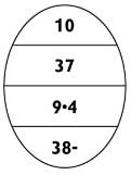
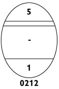
Less than one tenth of ice to show open water. Some thick first-year in small floes; new ice is also present and has no floe form.
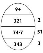
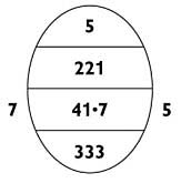
Description:
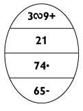
9+/10 total ice concentration. 3/10 old ice in small floes, 2/10 thick first-year ice in medium floes, 1/10 thin first-year ice in small floes, 2/10 grey-white ice in small floes, and the remaining 2/10 is new ice with no floe form.
Description:
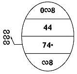
4/10 of old ice in medium floes. New ice is also present with a concentration of less than 1/10.
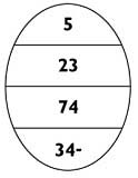
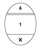
Description:
5/10 total ice concentration. 2/10 thin first-year ice in small floes and 3/10 grey ice in medium floes.
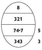
Description:
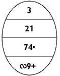
9+/10 total ice concentration. 3/10 old ice in big floes, 4/10 first-year ice in medium floes and 3/10 young ice with floes undetermined. Horizontal lines with no egg shell indicates that data has been interpreted from radar
3.8.2 Strips and Patches
Description:
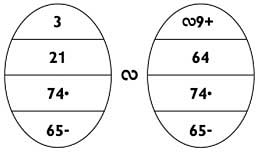
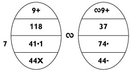
3/10 total ice concentration in strips and patches of 9+/10. 6/10 old ice in vast floes and 4/10 thick first-year ice in big floes. These floe sizes are significant and warrant the use of two ovals.
Description:
9+/10 total ice concentration comprised of 1/10 thick first-year ice, 1/10 medium first-year ice, 8/10 new ice and old ice with a concentration of less than 1/10. The old and thick first-year ice are distributed throughout the area in strips and patches made up of 3/10 old and 7/10 thick first-year ice. All ice types in the second oval must be included in the first oval.

3.8.3 Brash
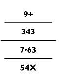
Description:
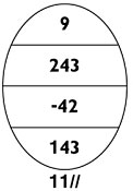
9/10 total ice concentration. 2/10 brash (1/10 very thick brash, 1/10 thick brash and a trace of medium and thin brash), 4/10 grey ice in medium floes and 3/10 nilas in small floes.
Description:
6/10 total ice concentration. 4/10 brash (1/10 medium, 1/10 thick and 2/10 very thick) and 2/10 nilas in small floes.
The above information is © Government of Canada and the original can be viewed at Manual of Ice (MANICE) – Canada.ca